
The drive systems of EV are mainly made of 3 units, the electric drive assembly (motor), the energy control hub (electronic control system), and the power transmission hub (reduction gear). As heart of the vehicle, the motor converts electrical energy into mechanical energy through electromagnetic induction, and this process highly relies on one key component of the motor system, the stator winding.
From two main perspectives of materials science and electromechanical engineering, we focus on the “energy hub” of the powertrain in EV to have a deeper understanding of technical principles and process innovations behind it.
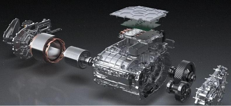
Pic. 1 electric drive system
The stator winding serves the role of foundation for electromagnetic energy conversion. The winding wire of the motor is made of high-purity oxygen-free copper, through precision winding processes, the wire is made into multi-phase, spatially symmetric coil groups. Thus a 3-dimensional electromagnetic field matrix is built by employing distributed winding topologies (such as lap or wave winding configurations), furthermore the electromagnetic excitation core of the motor stator system is built.
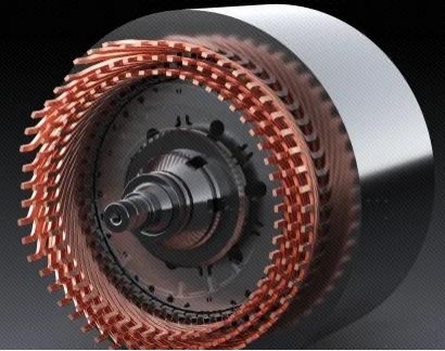
Pic. 2 stator & rotor assembly
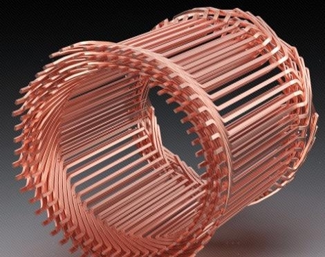
Pic. 3 stator winding
The electromagnetic conversion mechanism is as follows: Under PWM variable-frequency current drive, the MMF-generating windings produce a spatiotemporal vector-synthesized magnetic field, which dynamically couples with the rotor permanent magnets through the MMF angle. The electromechanical coupling is based on the Maxwell stress tensor principle. A tangential electromagnetic force is generated between the stator and rotor magnetic fields, driving mechanical torque output. The energy transfer chain undergoes a three-stage conversion process: electrical energy → magnetic energy (winding energy storage) → mechanical energy (rotor kinetic energy).
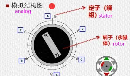
Pic. 4 principle of motor
01. Geometric Revolution — high filling ratio of flat magnet copper wire
The electric drive in EV with advantages of high efficiency, a compact design, and high power density have been regarded as completely competitive. As the core of energy conversion, stator winding technology has undergone two generations of material system iteration: from traditional round copper wire windings (0.5–2.0 mm in diameter) to flat copper wire windings (with cross-sections from 0.8×3 mm² to 2×6 mm²).
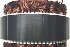
Pic. 5 stator-round winding wire
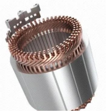
Pic.6 stator-flat winding wire
The core advantage of flat winding wire lies in “slot fill factor,” a key indicator for evaluating stator windings. The formula for calculating the slot fill factor (K) is:
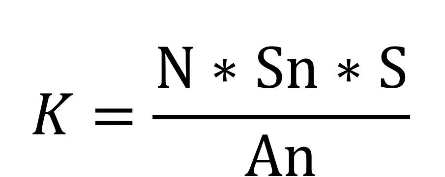
Where N is the number of parallel strands; Sn is the number of conductors per slot; S is the cross-sectional area of a single conductor; and An is the effective cross-sectional area of the stator slot. If the stator slot of a motor is compared to a “container,” then the slot fill factor is a measure of how full this container is with “payload.” Imagine this scenario: round wire windings are like glass marbles casually poured into a box—their round shapes always leave awkward gaps between them. This is why traditional round wire has a slot fill factor of only 40%–60%. A large amount of space is wasted by air and insulation materials, like an express box stuffed with bubble wrap: it looks bulging on the outside, but is actually “bloated.” Flat copper wire windings, by contrast, are like a master of space management. Their rectangular cross-sections fit snugly into the straight boundaries of the stator slot, striving to fill every millimeter of gap. When these flat conductors are stacked layer by layer at precise angles, it is like playing a jigsaw puzzle: the corners and crannies originally wasted by circular arcs are now filled by the sharp edges of the flat copper wire, and the slot fill factor shoots above 70%.
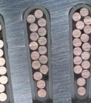
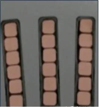
Pic. 7 comparison of te filling of round and flat wire
What’s even better is tha the high filling ratio makes previous empty space now occupied by conductive copper, equivalent to increase of 30% more “energy carriers” into the same volume, allowing current to flow more smoothly. This not only reduces “traffic jams”—resistive losses—but also improves transport efficiency—power density.
02 Cooler and Quieter — The Thermal and Acoustic “DNA” of Flat Copper Wire
Temperature rise has been an issue that restricts performance for motors. In traditional round wire windings, gaps between conductors force heat to conduct slowly through layer upon layer of insulation, making localized hot spots highly likely. Flat copper wire, by means of “contact cooling,” creates a new heat conduction path, thereby reaching a new level in temperature control. This new heat conduction path features a bidirectional composite cooling direction: first, axial cooling, in which the motor’s internal oil circuit directly cools the end windings, reducing the end temperature and thereby indirectly removing heat generated by the flat copper wire inside the core, establishing a fast axial cooling path; second, radial cooling, in which multiple layers of flat copper wire are in radial contact with one another, allowing heat to transfer radially between the copper wires, preventing heat from accumulating locally and creating localized high temperatures.
As shown in Pic. 8 and 9, the conductor cross-sectional distributions at the end portions and in the cross-sections are compared between round wire and flat wire. It can be seen that the air circulation inside the round copper wire is relatively confined, while the flat copper wire provides more space for air circulation. In addition, the contact between the round copper wire and the slot wall is line contact, whereas the contact between the flat copper wire and the slot wall is surface contact, which makes the flat copper wire more effective in heat convection and heat conduction. Specifically, the heat dissipation area of the flat copper wire is increased by 30% compared with that of the round wire. Under the same operating conditions, the temperature rise of the flat-wire motor winding is about 10°C lower than that of the round-wire winding.
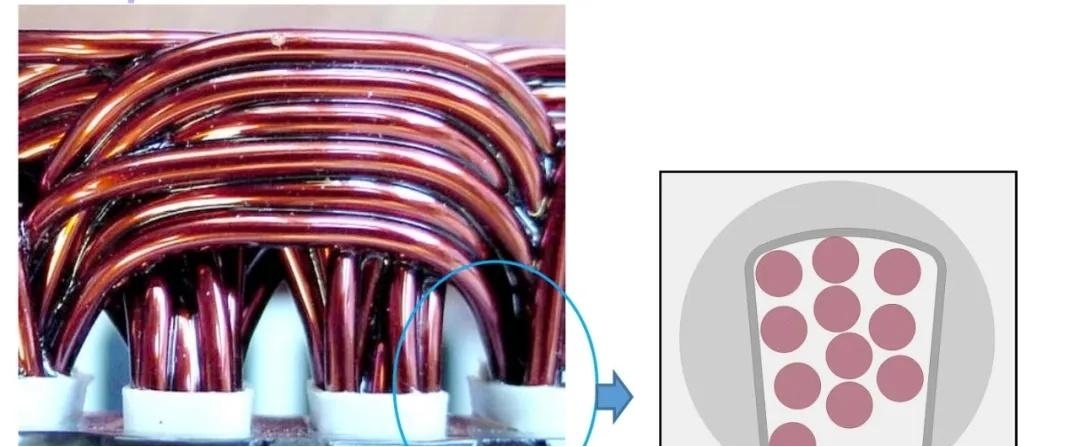
Pic.8 round wire winding
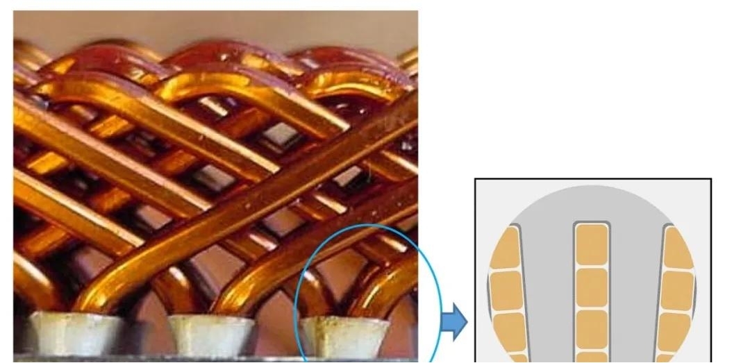
Pic.9 flat wire winding
In terms of NVH, flat copper wire also has significant advantages over round copper wire. The flat copper wire motor uses rectangular conductors arranged tightly; this “planar close-packed” structure reduces the winding end height by 20%–30%. Moreover, after the flat copper wire winding is formed, the end structure stiffness is much higher than that of round copper wire, reducing the risk of structural resonance caused by electromagnetic force. Compared with the “loose bundling” form of round wire motors, the gap between flat wire windings is reduced by more than 50%, effectively suppressing high-frequency micro-vibration between conductors.
In addition, the flat wire winding adopts a multi-layer insulating varnish coating technology (Radius coverage > 95%), which reduces air turbulence noise caused by burrs on the conductor surface compared with round copper wire. Its compact structure makes the electromagnetic field distribution more uniform, effectively reducing core vibration caused by the magnetostriction effect. The high-frequency components in the 2–4 kHz range of the overall noise spectrum are reduced by 60%. Test shows that under the 3000 rpm operating condition, the sound pressure level of the flat wire motor is 3–5 dB(A) lower than that of the round copper wire motor.
03 Stunning performance in Energy Efficiency
Flat winding wire stands out with three core advantages:
- Increased slot fill factor leads to a simultaneous reduction in copper loss.
Rectangular cross-section can tightly fill the stator slots. Its slot fill factor is 20–30% higher than that of round-wire motors. At the same volume, the copper cross-sectional area is larger, and the resistance is significantly reduced (formula: R = ρL/S). This alone can reduce copper loss (which accounts for more than 60% of total losses) and improve efficiency by more than 1%. At the same time, the high slot fill factor increases the power of a motor of the same volume by 20–30%, and the heat-dissipation contact area is increased. Its heat conduction capability is 1.5 times that of round wire, and the temperature rise is reduced by 10%, avoiding efficiency degradation caused by high temperatures.
2 breakthrough in solving skin effect at high frequency
The skin effect is the phenomenon in which current concentrates near the surface when alternating current passes through a conductor, and it becomes more pronounced as the frequency increases. Taking 10 kHz as an example, the diameter of round wire (1.6–2.5 mm) far exceeds the skin depth (0.73 mm), resulting in a reduced effective cross-sectional area and a sharp increase in resistance, with high-frequency copper loss accounting for more than 40%. In contrast, flat winding wire has a thickness of only 1–1.5 mm, a higher proportion of skin depth, more uniform current distribution, and a 60% reduction in AC loss. Especially after the widespread adoption of 800V high-voltage platforms and silicon carbide (SiC) devices, flat wire has become the core solution for suppressing high-frequency losses above 10 kHz.
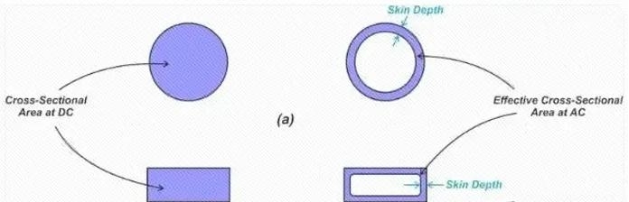
Pic. 10 “skin effect” of round and flat conductors
3 Distributed Winding Technology Balances Eddy Current Loss
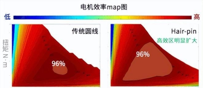
The flat wire motor adopts a “hairpin winding + periodic transposition” design. The conductor positions are rotated every 6–8 stator slots, keeping the difference in magnetic field strength experienced by each conductor within 5%. This effectively balances the eddy current distribution, thereby further reducing iron loss by 20%. This design offers unique advantages: it not only uses the low-resistance characteristics of flat wire to reduce DC loss, but also suppresses AC loss by optimizing the magnetic field distribution, achieving loss reduction in two dimensions. By comparing the efficiency maps of traditional round copper wire motors and flat copper wire motors, it can be seen that the proportion of the 96% high-efficiency area of the round copper wire motor is only about 20% of that of the flat copper wire motor.
Pic. 10 “skin effect” of round and flat conductors
3 Distributed Winding Technology Balances Eddy Current Loss
The flat wire motor adopts a “hairpin winding + periodic transposition” design. The conductor positions are rotated every 6–8 stator slots, keeping the difference in magnetic field strength experienced by each conductor within 5%. This effectively balances the eddy current distribution, thereby further reducing iron loss by 20%. This design offers unique advantages: it not only uses the low-resistance characteristics of flat wire to reduce DC loss, but also suppresses AC loss by optimizing the magnetic field distribution, achieving loss reduction in two dimensions. By comparing the efficiency maps of traditional round copper wire motors and flat copper wire motors, it can be seen that the proportion of the 96% high-efficiency area of the round copper wire motor is only about 20% of that of the flat copper wire motor.
Post time: Sep-22-2026


